Bench Program Your Servo
Because of its high degree of accuracy, the AeroPerfect™ Digital Control Throw Meter is extremely useful when programming Hitec Digital servos. We at Bell Electronic Technologies have developed two methods for programming Hitec Digital servos using the AeroPerfect™ Digital Control Throw Meter: One that is adapted for "on the bench" and one for "on the plane". The following procedure describes the "on the bench" method. Click here for the on the plane method. Also please note that AeroPerfect's new MU-9000X USB and MU-9000X AP3 can also be used while following this servo programming procedure. In the following text, just substitute MU-1800-I with either of these two newer devices.
By using the following procedure, you can bench program your Hitec digital servos using the Hitec HFP-10 programmer without resorting to the "trial and error" method. (We are not in any way affiliated with Hitec. We just wanted to share with you a method that has worked for us!) Please read our Conditions of Use
Please use this Servo Calibration Spreadsheet along with this procedure. Downloading of this spreadsheet indicates that you agree with the Conditions of Use at the bottom of this page. You can either "right-click" and select "save target as" or "save link as", depending on your browser.
In the following example, a Hitec HS-5645MG is programmed with the Hitec HFP-10 digital servo programmer. The AeroPerfect™ Digital Control Throw Meter is used to accurately measure the angle of the servo arm. The initial values in the spreadsheet were obtained while using an Eclipse 7 radio with EPA's set to 115%.
Programming Overview
This procedure takes into account the difference (if any) between your radio's pulse widths and the pulse widths assumed by the HFP-10 programmer for all radios and calculates an appropriate ratio. A preliminary set of calibration numbers are obtained from the HFP-10 programmer based on this ratio. These numbers are tested by using your radio and accurately measuring the servo arm angles with your AeroPerfect™ Digital Control Throw Meter. The final programming numbers are then calculated by the spreadsheet based on the measured angles.
Before we get started, we'd like to say a word about about the direction of rotation. CW (clockwise) and CCW (counter-clockwise) is mentioned in two contexts within this procedure: One describes which direction the servo arm is rotating, while the other refers to the direction programmed by the HFP-10 (Program CW/CCW).
If you program your servo for CW (clockwise servo rotation) using the HFP-10, it means that wider pulse widths will cause CW servo rotation. (Conversely, narrower pulse widths will cause CCW servo rotation). Also, if you program your servo for CCW (counter-clockwise servo rotation) using the HFP-10, it means that wider pulse widths will cause CCW servo rotation. (Conversely, narrower pulse widths will cause CW servo rotation). On our Eclipse 7 radio (with all of the channels set to "normal" NOT "rev") we've observed that, with the servo directions set to "normal", that left stick movement produces narrower pulse widths and down stick movement also produces narrower pulse widths (and the converse of this is true as well).
Let's get started!
Program Your Radio
Step 1:
Set the trims and sub-trims on all channels of your transmitter to zero and make sure the EPA adjustments are where you plan to use them (e.g., 100% or 115%) for all channels. Also, make sure you don't have any mixes activated. (There is an advantage in setting your EPA's near your radio's maximum in order to gain resolution. You can even set your radio's EPA's to maximum, however if you end up needing a greater control throw range, the servo would have to be reprogrammed.) Choose the direction for the radio channel you plan to use. With your radio control stick at neutral, push the servo arm onto the servo spline. Make sure it is at 90 degrees to the servo case. Use your radio's sub-trim function if necessary to set the servo arm at the desired angle (usually 90 degrees to the servo case).
Measure Your Radio's Pulse Widths
Step 2:
Connect the HFP-10 to the radio channel you plan to use. Select the Measure Pulse program function. With the control stick at neutral, enter the number of microseconds into the spreadsheet on the "Measure Radio's Pulse Widths" row and in the "Middle" column. Move your radio's control stick in the direction that will yield the smallest pulse width and enter that value into the spreadsheet on the same row, but in the "CW Degrees" column. Lastly, move your radio's control stick in the direction that will yield the largest pulse width and enter that value into the "CCW Degrees" column.
At this point, the spreadsheet shows two scale factors that will be used later to obtain the "Initial Program Numbers".
Test Fixture
Step 3:
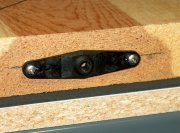
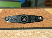
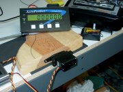
In order to bench program your Hitec Digital servo, you'll need to make a test fixture. The test fixture is extremely simple since we won't be needing protractors, tape, machined arms, or pointers. Simply attach one of the many extra plastic arms you have lying around to a flat piece of wood as shown below. Not shown in picture, but C-clamping the flat piece of wood to the workbench is recommended.
Initial Spreadsheet Values
Step 4:
Reset the servo using the Program Reset function on the HFP-10. After resetting the servo, make sure you set the desired direction of of servo rotation using the Program cw/ccw function at this time. Please refer to the CW - CCW discussion above in deciding the direction of rotation.
Enter the direction of rotation and the desired angular range into the spreadsheet. Remember that the +/- values don't have to be the same (e.g., they could be 15 degrees CW and 22 degrees CCW).
Install Servo Into Test Fixture
Establish A Zero
Step 5:
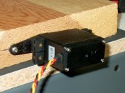
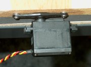
Remove the servo arm that you plan to use and set it aside in a safe place (you want to use this same arm after programming your servo). Set the HFP-10 to the S-Test Manual program function and set the knob for the number of microseconds that you measured for neutral in step 2 (Probably somewhere close to 1500 microseconds). Push the servo shaft into the plastic servo arm of the test fixture so that the servo case is reasonably parallel to the test fixture servo arm.
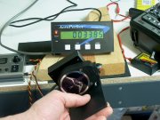
Hold one end of the MU-1800-I measuring plate onto the servo case and obtain a zero angle reference by pushing the reset button on the AeroPerfect™ AP3 display (Please utilize the measurement plate for this step rather than placing the MU-1800-I directly onto the servo case without the plate. This will prevent any interaction between the MU-1800-I damping circuit and the servo).
Obtaining Initial Programming Numbers
Step 6:
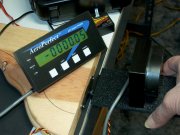
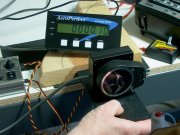
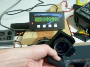
Select the Program EPAneuFS program function. In preparation for the next few steps, here are a few more photos that provide an overview of the test setup:
(Click Thumbnails for Larger Picture) |
|
|
|
Step 7:
Hold the measuring plate of the AeroPerfect™ MU-1800-I onto the servo case and rotate the HFP-10's knob until you reach zero on the AeroPerfect™ AP3 display (photo is incorrect and should be showing zero here). Enter the initial program number from the HFP-10 display into the spreadsheet under the "(M)" column and on the "Initial Program Numbers" row. Push the "M" button on the HFP-10.
Step 8:
Continue to hold the measuring plate of the AeroPerfect™ MU-1800-I onto the servo case and rotate the HFP-10's knob left until the AeroPerfect™ AP3 display reads the calculated value from the spreadsheet on the "Initial Numbers Based On" row (and under the "CW Degrees Column"). Enter the initial program number from the HFP-10 display into the spreadsheet under the "UP/L" column (and on the "Initial Program Numbers" row). Press the UP/L button.
Step 9:
Continue to hold the measuring plate of the AeroPerfect™ MU-1800-I onto the servo case and rotate the HFP-10's knob right until the AeroPerfect™ AP3 display reads the calculated value from the spreadsheet on the "Initial Numbers Based On" row (and under the "CCW Degrees Column"). Enter the initial program number from the HFP-10 display into the spreadsheet under the "DN/R" column (and on the "Initial Program Numbers" row). Press the DN/R button.
Measure the Error
Step 10:
Disconnect the servo from the HFP-10 and connect it to your receiver. Holding the AeroPerfect™ MU-1800-I measuring plate as described previously, measure the angles of the servo case as you move the radio's stick from neutral, to full left and full right. Enter the angular values into the spreadsheet on the "Measured Angles Using Radio" row. Be sure to enter the values in either the "CW Degrees" or the "CCW Degrees" column, depending on which way the servo case is rotating (not whether the AeroPerfect™ AP3 is displaying a positive or negative number).
For your radio's neutral stick position, take note of any error from zero. If the error you measured is that the servo arm is too far CW (Clockwise), enter a positive angular value into the spreadsheet. Otherwise, if the error you measured is that the servo arm is too far CCW (Counter-clockwise), enter a negative angular value into the spreadsheet. Again, use the "Measured Angles Using Radio" row and the "Middle" column.
Program the Final Calibration Numbers
Step 11:
The spreadsheet now has the final calibration numbers. Use the Program EPAneuFS program function to program the "Predicted Numbers" from the spreadsheet. Rotate the knob until the predicted number for "M" shows on the HFP-10 display. Push M. Then rotate the knob left until the predicted number for "UP/L" shows on the display. Push UP/L. Rotate the knob right until the predicted number for "DN/R" shows on the display. Push DN/R.
Make Final Control Throw Measurements
Step 12:
Disconnect the servo from the HFP-10 and connect the servo to your radio receiver. Use the AeroPerfect™ MU-1800-I as before to measure your desired zero angle and to verify the servo case rotation in both directions.
You have now successfully bench programmed your Hitec digital servo using your AeroPerfect™ Digital Control Throw Meter ! Remember to re-attach the same servo arm that you used in step 1. You may want to print out the spreadsheet at this time for future reference. HAPPY FLYING!
Conditions of Use
This calibration procedure and the accompanying servo calibration spreadsheet are provided by Bell Electronic Technologies "as is". In no event shall Bell Electronic Technologies be liable for any direct, indirect, incidental, special, exemplary, or consequential damages arising in any way from the use of this procedure and/or spreadsheet.
This procedure and spreadsheet are for private use and may not be used by any other commercial entity. User agrees not to sell this procedure and/or accompanying spreadsheet. User may freely download and distribute this procedure and accompanying spreadsheet as long as these conditions of use are met. User may link to this procedure and/or spreadsheet.
Any express or implied warranties, including, but not limited to, the implied warranties of merchantability and fitness for a particular purpose are disclaimed.
© 2004 - 2012, Bell Electronic Technologies All Rights Reserved
